Large Quadcopter Build

Large Quadcopter Build

    ›Miscellaneous

    Build

    • Introduction
    • Parts
    • Purchase Order
    • Batteries
    • Transmitter - Getting Started
    • Stick setup
    • Transmitter - Model Setup
    • Transmitter - Flight Modes
    • Receiver
    • Assembling the electronics
    • Binding the receiver
    • Pixhawk setup
    • F450 frame kit
    • Soldering the PDB
    • Frame assembly
    • Final assembly
    • Final assembly
    • Final setup

    Appendices

    • Pixhawk LEDs
    • Pixhawk tones
    • Pixhawk Windows device driver
    • Transmitter extras
    • Soldering
    • Stores
    • Windows VM
    • OpenTX Companion on Ubuntu
    • QGroundControl
    • Notes

    FPV quad

    • Eachine QX95
    • Inprogress QX95
    • Cleanflight Settings README
    • X-racer notes

    Followup projects

    • Video
    • Telemetry

    Miscellaneous

    • Snippets
    • Antenna mount
    • Antenna mount - version 1
    • Antenna mount - version 2
    • F450 dimensions
    • GPS mast placement
    • Notes to self
    • Pages and videos
    • Power module - XT60 To Deans
    • Receiver power
    • Receiver Windows upgrade
    • Inside the RX8R
    • Unused parts
    • Vibration damping
    • OpenTX sounds
    • Flight mode sounds
    • Case
    • Foam Outline README
    • 20181021 Rebuild Params README
    Edit

    Inside the RX8R

    The RX8R consists of a primary PCB and a radio submodule.

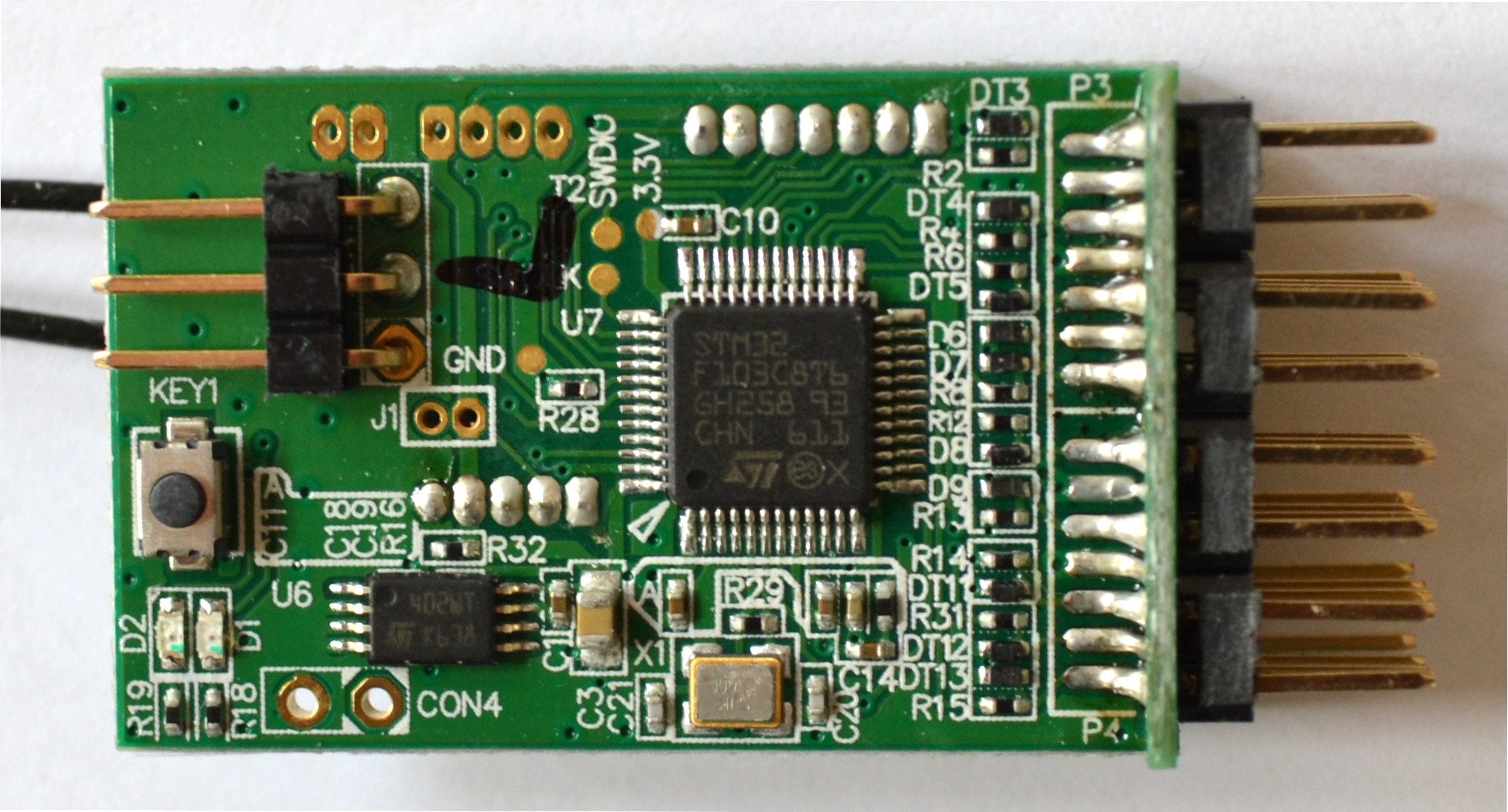
    The top of the primary PCB has the F/S switch, several pads - GND, 3.3V, SWCLK and SWDIO (the text for SWCLK is largely obscured by a black mark) - and two sets of connections labelled CON4 and J1.

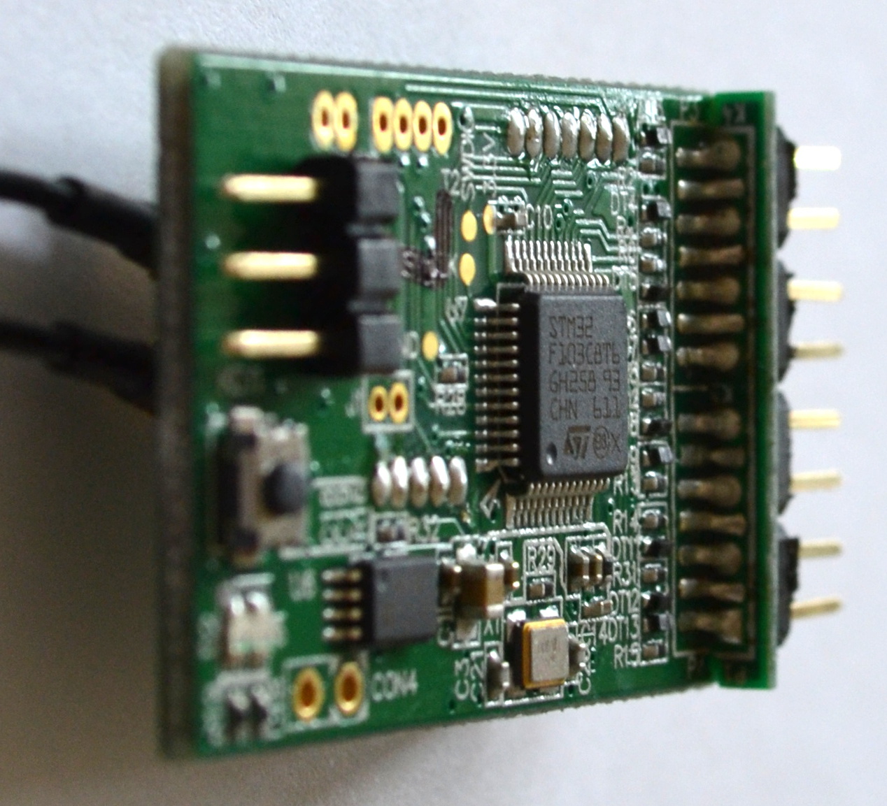
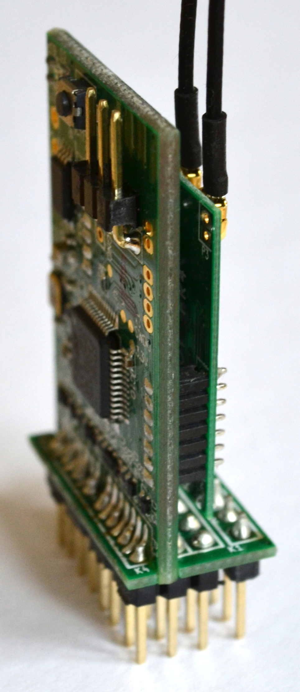
    Primary PCB from the side (Smart Port pins are to the left).

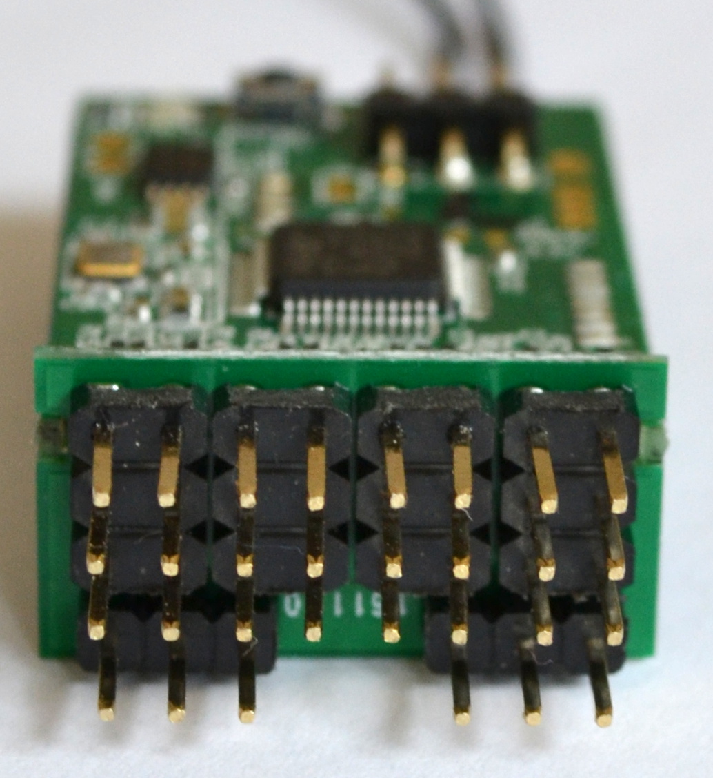
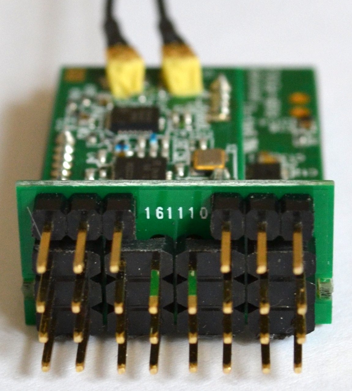
    Servo pins with the two S.BUS ports at the bottom.

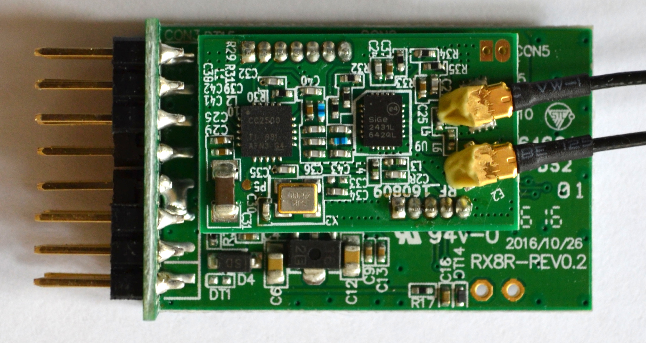
    Radio submodule on underside of primary PCB.

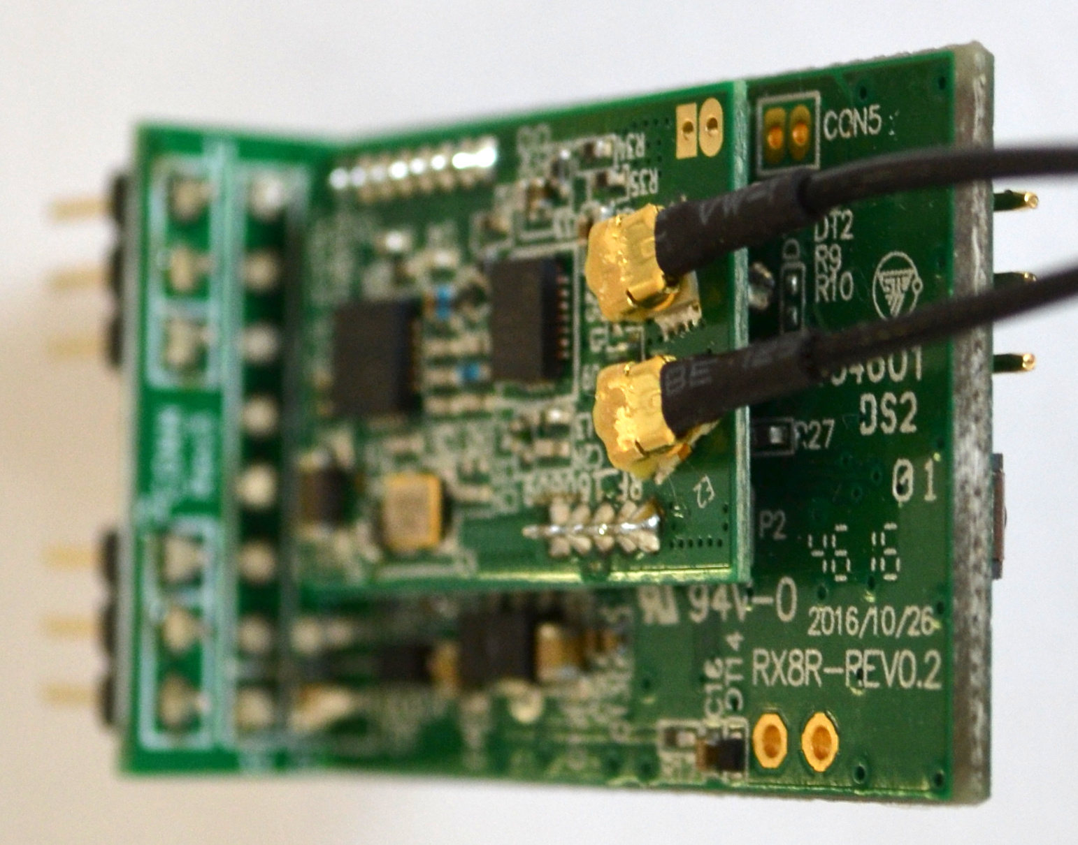
    Radio submodule on underside of primary PCB from right side.

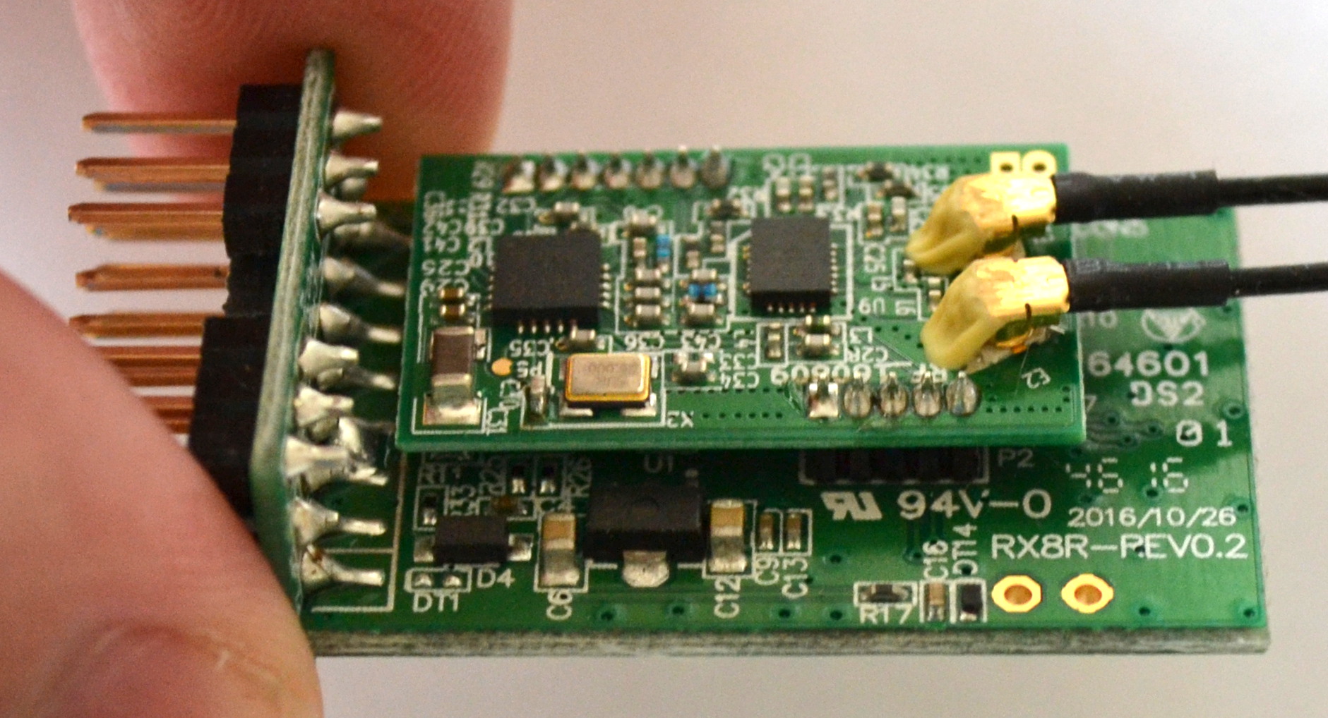
    Radio submodule on underside of primary PCB from bottom edge.

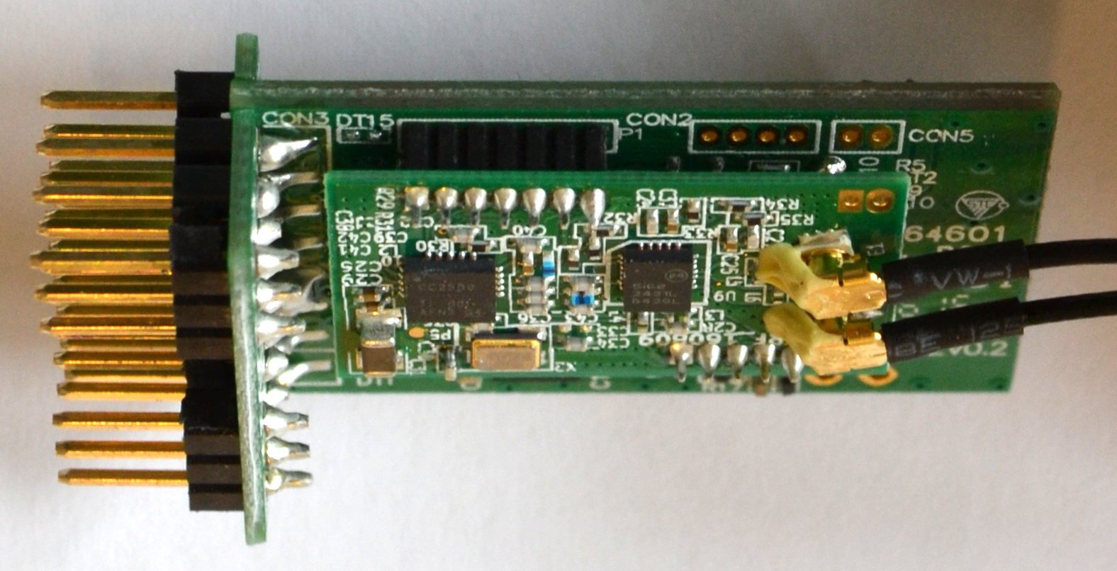
    Looking at the radio submodule from the top edge we can see two more sets of connections, these ones labelled CON2 and CON5.

    Servo pins with the two S.BUS ports now at the top.

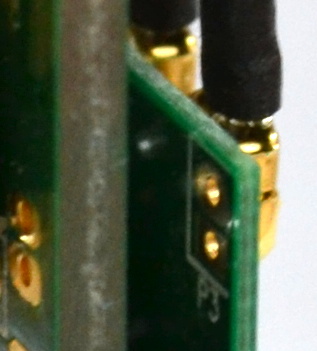
    Looking at the underside of the radio submodule one can just make out another set of connections, labelled P3.

    Closeup of P3.
    P3 closeup

    Last updated on 1/16/2019
    ← Receiver Windows upgradeUnused parts →